Lint generation and its removal from the knitting area has been a nagging problem for the knitting industry world over with no complete and effective solutions in sight. To solve lint problems, various companies from all over the world have offered their solutions from time to time, but they all have proven to be incomplete in one way or the other. Mukesh Gupta, an accomplished designer of knitting plants and a specialist in lint extraction techniques, has developed a new and effective design of lint extraction from circular knitting plants, along with Arjun Aggarwal. The all-embracing new way and a completely effective solution for lint extraction is proposed to increase the effectiveness of return air systems, i.e. numbers of air replacements per hour and at the same time reduce the power consumption. A patent for this design has also been applied for.
The new configuration exhibits a massive increase in efficiency and effectiveness of the return air system in terms of the number of air replacements per hour, achieved by reducing the volume of spaces around the creel and its associated knitting machine
Lint continues to plague circular knitters of spun yarns worldwide. In spite of solutions for lint like expensive filter creels from Memminger IRO and Martex, or other localized extraction solutions from companies such as Alandale and Mayer & Cie, most solutions are incomplete. As such no complete and universal solution for lint extraction is available or applied worldwide. Some knitting companies have installed expensive power guzzling solutions such as return air systems from Luwa, which has eventually proven to be partially effective against generated lint and its associated problems.
In the return air systems ordinary air or humidified air is injected into the plant from ducts placed on the ceiling and this return air is exhausted from trenches placed below the floor. As a result, the air in the production floor is replaced by fresh air, and the air being exhausted carries away airborne contaminants in the plant. Return air can be cooled or humidified to create desired conditions on the production floor. Numbers of air replacements per hour are determined by:
Volume of air being injected / Volume of plant
However, return air system provides one distinct advantage of carrying the lint generated to its lint trapping filters, which are cleaned automatically, without requiring any effort on part of operators. This one advantage needs to be exploited. The use of return air system needs a redesign to reduce its power consumption and to increase its effectiveness or efficiency.
Prior Art and the problems with Lint
It is well known that creels are a major source of lint generation particularly during cone unwinding and there is a tendency for lint to be shed at points where the yarn touches any part of the tubes conveying the yarn to the knitting machine. It is well known that lint is shed in the knitting machine at various points such as IRO’s (the positive yarn feed wheel system, which ensure a constant rate of supply of yarn to a knitting machine), feeders, needles and sinkers. The lint so generated during knitting accumulates on various locations on the knitting machine. Once the fabric roll is complete, it is doffed from the knitting machine. Prior to starting a new fabric roll, the knitting machine is thoroughly cleaned manually by blowing compressed air on the points on which lint has accumulated on the knitting machine. Compressed air pressure dislocates and discharges this accumulated lint to the air surrounding the knitting machine. The lint thus becomes air borne contaminating the working environment and giving rise to many problems.
Air borne lint migrates to knitting zones of adjacent knitting machines and gives rise to faults in fabrics being knitted and consequential loss in production. In order to deal with this problem, return air systems are deployed which are power guzzlers, by which huge volume of air is continuously injected and exhausted from the knitting area. The return air moves lint to the lint trapping filtering systems. Return air is faulted on many accounts, air velocities are quite low, the number of air replacements per hour is less and directly proportional to the power consumed, air cannot be made to follow a desired path in or around a knitting machine; additionally making it an entirely energy intensive operation.
The knitting machine and its associated creel is totally isolated from adjacent machines, eliminating all cross contamination issues. This is much desired when knitting yarns with different types of fibres and/or coloured and mélange yarns
Primarily, the return air system is not able to prevent cross contamination, i.e. if one knitting machine is being blow cleaned by compressed air, then the lint which is blown off in the environment is carried to adjacent knitting machines, causing contamination.
Cross contamination, however is mitigated by using polythene curtains, which help to contain airborne lint, but use of polythene curtains present other problems such as obstruction in air flow path, static build-up which causes lint to stick to the polythene curtains and the affinity of polythene for dust accumulation is well known.
Other solutions include filter creels, in which creels are encased in an enclosure through which air flow is created. The air flow entrains most of the lint generated in the creel and the lint is then removed by a filtering process. This however does rely upon the filter being cleaned regularly, which as such is a time-consuming process. Enclosed creels present operational difficulties. Access to parts or loading of yarn cones or mending yarn breaks or tailing is problematic and restrictive. Filter creels consume power. The lint generated in the filter creel is arrested but there is no solution for the lint that is generated on the knitting machine, which is blown off from the knitting machine to the surrounding air by fans and compressed air.
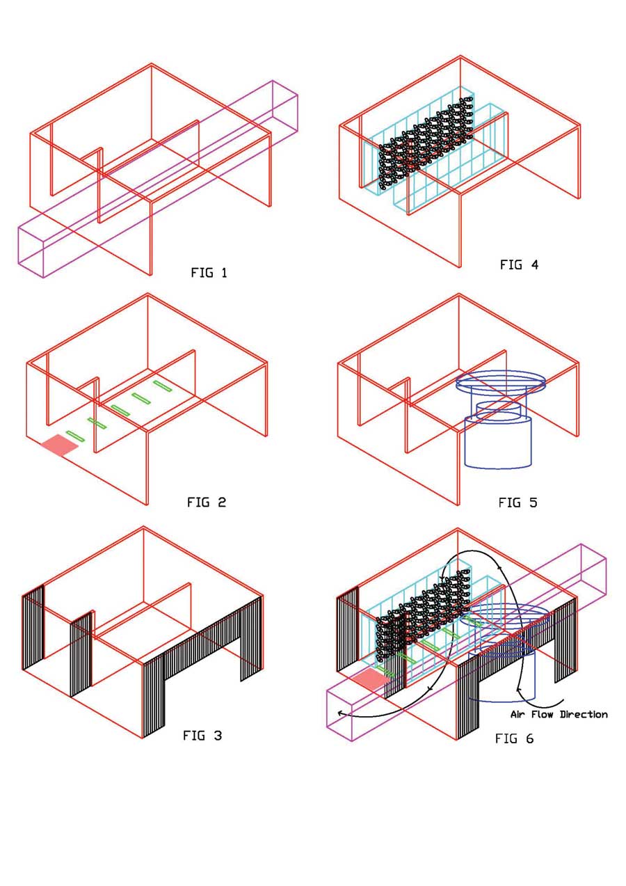
To address the above problems, a new design is proposed for laying out creels and circular knitting machines and their integration with the return air system for a total and a complete solution for lint removal with least energy consumption and low capital investment. [See schematic diagrams numbered 1 to 6 on the opposite page].
Working of the Proposed Layout Design
Each knitting machine and its associated yarn creel are placed within an enclosure (coloured red). Therefore total isolation from adjacent machines is achieved and all cross contamination issues are totally eliminated. Each knitting machine and its associated creel is placed on top of the return air trench (coloured magenta) and is integrated with the return air system with floor slits (coloured green) and trap door with closed slits (coloured pink). Lint extraction is affected by the constantly flowing return air through enclosure (coloured red) by air flow direction of which is labelled as “Air Flow Direction”.
Since return air is being extracted from below the creel area, hence return air is forced to enter from the openings left in the PVC curtains (coloured black) in front of the knitting machine. Air flow has now been given a direction and is sweeping the knitting machine and is extracting lint, being generated at various points within the knitting machine. This same very air flow is also trapping and extracting the lint being generated in the creel due to cone unwinding prior to being exhausted into the return air trench.
The extracted lint is carried by the return air to the filters of the return air system. These filters are cleaned automatically with automation and no manual intervention is required by operators. Hence operators have been spared of the tedious tasks of frequently cleaning lint filters. Fabric rolls are removed from the front of the enclosure (coloured red); yarn cones are loaded into the creel from the back of the creel area and yarn breaks are mended by entering the creel area from front of the creel area through self-sealing PVC curtains (coloured black). After completion of each fabric roll the knitting machine is stopped, the completed roll is doffed and lint settled on the machine is manually blow cleaned.
During this cleaning operation, the closed slits in the trap door (coloured pink) are automatically opened, causing increase in slit orifice size, resulting in greater flow volume of return air flow, this increases air velocity. The lint that is blown off the knitting machine during blow cleaning operation is not allowed to escape outside of enclosure (coloured red) and is arrested within the knitting machine area by walls of enclosure (coloured red) and by PVC curtains (coloured black). Increase in volume of return air flow with higher air velocities extract the airborne lint faster into the return air system. Hence, cross contamination problems caused due to lint being blown off during machine blow cleaning operation is contained. Lastly, the volume of creel section and the knitting machine section within the enclosure (coloured red) have been fixed and reduced substantially. For a fixed volume of return air flowing through enclosure (coloured red), the number of air replacements per hour depends on the volume of these individual enclosures. The smaller the volume of these enclosed areas, higher is the number of air replacements per hour, thereby increasing return air efficiency and consequently power consumption of the return air system is reduced and optimized. The key to increasing return air efficiency lies in the actual achieved number of air replacements per hour.
Nine Distinct Advantages of this Configuration
- All the problems mentioned earlier have been obviated or mitigated by this unique arrangement of setting up creel, knitting machine, its enclosure and integration of the same into the return air system.
- This new configuration exhibits a massive increase in efficiency and effectiveness of the return air system in terms of the number of air replacements per hour, achieved by reducing the volume of spaces around the creel and its associated knitting machine.
- The lint created during the blow cleaning of the knitting machines by compressed air is totally confined and encapsulated by arresting and confining the airborne lint to a specific defined space.
- Elimination of other lint collecting devices such as filter creels, leads to elimination of all efforts required by operators for cleaning the lint-trapping filters of these devices, saving on power consumption and capital investment.
- The new design makes it possible to generate a desired flow path of return air, thereby allowing manipulation and control of air flow direction as per the exact requirement of the lint extraction process.
- Increase in the volume of the return air flow or the air velocity during blow cleaning of the knitting machine. The increased air flow volume/velocity are beneficial to fast extraction of air borne lint blown off into the surroundings by compressed air during the machine blow cleaning operation.
- The knitting machine and its associated creel is totally isolated from adjacent machines, eliminating all cross contamination issues. This is much desired when knitting yarns with different types of fibres and/or coloured and mélange yarns.
- The system is maintenance-free and requires no attention or care after installation.
- This new design features reduction of power consumption of the return air system to fewer than 850 watts of power to extract lint from one knitting machine and its associated creel. However, this configuration is limited to availability of return air system and cannot be implemented if return air systems are not installed.
Conclusion
This design is cost-effective, requiring low capital investment and totally eliminates cross contamination. This design reduces power consumption and increases return air efficiency substantially to almost an average of 56 air changes per hour in creel area and 36 air changes per hour in knitting machine area for a volume of 2700 m3 of return air flowing through each knitting machine per hour which can be generated by fewer than 850 watts of power consumption.
This design confines the air borne lint generated during machine blow cleaning to a restricted space and does not permit this airborne lint to migrate elsewhere to other adjacent knitting machines, completely preventing cross contamination and at the same time finds a completely ingenious solution for increasing velocity and volume of return air flow, required most for fast extraction of air borne lint generated during blow cleaning of knitting machines.
[The author can be contacted directly on mg@cleantech.in for any clarifications or questions.]