Different arrangements of machines in sewing lines are aimed towards optimal floor area utilization, better control, easier supervision, controlled installation and running costs, besides better housekeeping and conformance to compliance. There is no right or wrong layout as such; the aim is to maximize the use of floor area and easy manoeuvring of machines to achieve efficiency in production.
Prabir Jana and Y.P. Garg, in this article, analyse the advantages and disadvantages of different layouts by giving several machine layout plans to enable organizations to select the option best suited to their needs.
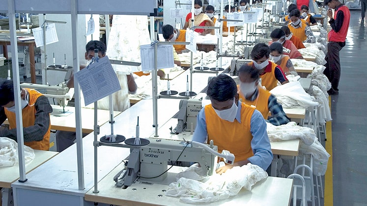
Plant layout or factory layout is an area under constant scrutiny by factory managers. Plant layout consists of cutting room layout, sewing room layout and finishing room layout. Although all departments are equally important, sewing room layout gets maximum attention. Two rows of sewing machine and centre table in-between is a common view in almost all factories. The origin of centre table is not known but it is probably meant to solve two problems together: to provide a cover to electrical wiring and also to act as material storage/transfer facility. However, sewing machines without centre table are also common these days and sewing machines with overhead material hanging system are increasingly becoming popular. During mid 80’s, there were some factories with conveyors (in place of centre table) in-between two rows of machines, but today motorized conveyors are no longer in existence.
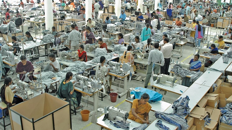
In fact, arrangement of a sewing machine depends on whether the layout is product-based or process-based. Few knitwear manufacturing companies follow process-based layouts while most follow product-based layouts. In process-based layout, similar types of machines are grouped together, where similar operations are carried out before passing on to the next group of operators. In product-based layout, machines are arranged based on sequence of operations derived out of operation breakdown and process flow chart. In product-based layout, whether sewing is done in PBU (Progressive Bundle Unit) system or UPS (Unit Production System), machines are arranged in a straight line. In PBU system, two columns of sewing machines are arranged either with a centre table in-between or pickup and disposal bins/trolleys by the side. Both forms of PBU layout are quite common and widely used with improvisation, wherever required.
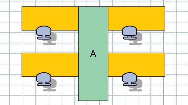
Layout ‘A’ is the most common method of arranging machines with centre table option; here all operators are facing in one direction. For one column of workers the centre table is on left, while for the other column of operators the centre table is on right, hence differential ease of bundle pickup and disposal. Centre table on the left side of the operator is always better for larger component. For operations involving a two component assembly where picking has to be done from both right and left of the operators, the service table at right is advisable, this is because additional extension space can be created at left side with comparative ease but creating additional space at right side of machine is difficult. Generally wiring is done underneath the centre table, and sewing machine motor is on right side of sewing machine table, so wiring for one column of sewing machine is cumbersome. Material movement in this type of layout is lateral/vertical/zigzag. Light source has to be separate for two columns of machine, thus infrastructure cost for lighting will be more. As operators are facing same sides (regimental seating) they are less prone to talk. The arrangement is ‘vaastu-friendly’.
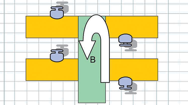
Layout ‘B’ is another common method of arranging machines. Here centre table is on the left side of both set of operators, hence easier pick up and disposal of bundles. Due to closeness of motor towards centre table, electrical wiring is easier. Here material movement is in ‘U’-shape or ‘return feed’ type. One column of operators move the material up the line and second column of operators move the material down the line. The cut component loading point and finished garment unloading point remain at the same point. As the needle points of two columns of operators are close to each other, light source can be common, thus cost of lighting infrastructure is lesser. As the operators are sitting face to face in adjacent columns, they are likely to indulge in talking and the layout remains non-friendly to ‘vaastu’.
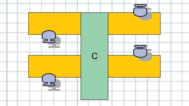
Layout ‘C’ is wrong re-arrangement of layout ‘B’, where the centre table for both columns of operators are on right side. This type of layout should be avoided.
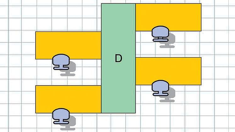
Layout ‘D’ is similar to layout ‘A’. However, the operator position (in comparison to layout ‘A’) is made alternate for easier pickup and disposal of bundles. Pickup and disposal space for each operator is staggered and separate, thus less claustrophobic. Space consumption at start and end of line is more than other options hence poor in space utilization.
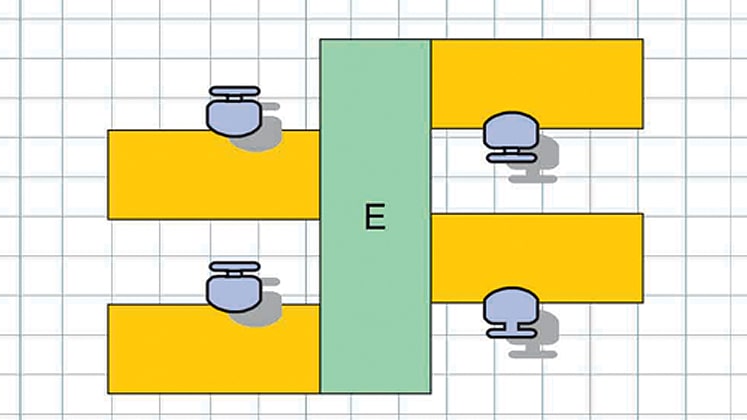
Layout ‘E’ is better arrangement of Layout ‘D’ and has a ‘U’ type of material movement like ‘B’. All the characteristics of ‘B’ type layout are applicable with additional advantage of having less claustrophobic material arrangement.
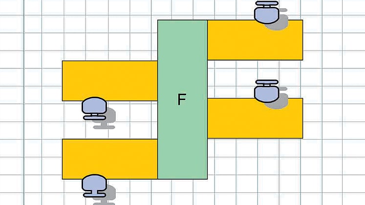
In Layout ‘F’, centre table is towards right side of operators resulting in inconvenient bundle pickup and disposal. This is a wrong arrangement of ‘E’ type and should be avoided at any cost.
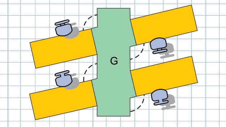
In Layout ‘G’, sewing machines are kept not in right angle to centre table but at an obtuse angle towards operator. Disposal point of preceding operator should always be the pickup point of succeeding operator. In this type of layout, disposal point of operator sitting behind is very conveniently located at the left side of the operator sitting at front. As the machines are arranged at an angle, the machine table gets an additional triangular space at left, which is always beneficial for large part sewing. Provision for gravity chute can be made at left of operator. Normally an angle of 105° to 120° is commonly maintained. However, more the angle, more is the space availability at left of operators. This non-regimental seating arrangement allows a lot of intangible benefits like non-monotonous, less tiring, less obstructive view, etc. Access to sewing machine by operators is comparatively better as more free space is available at the back of stool.
This angular layout is not commonly used in the industry due to various problems like difficulty in arranging machines at the specified angle, and making a triangular extension in centre table, besides also being a carpenter’s nightmare and having extremely high consumption of material and labour. A better option is to make a triangular extension in sewing table keeping the centre table straight and rectangular. If implemented, this can result in additional benefit over ‘B’ type.
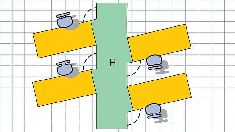
Layout ‘H’ is a modified type of Layout ‘G’ where machines are placed alternatively to make the material area staggered and less claustrophobic. All other characteristics of Layout ‘G’ are achievable here.
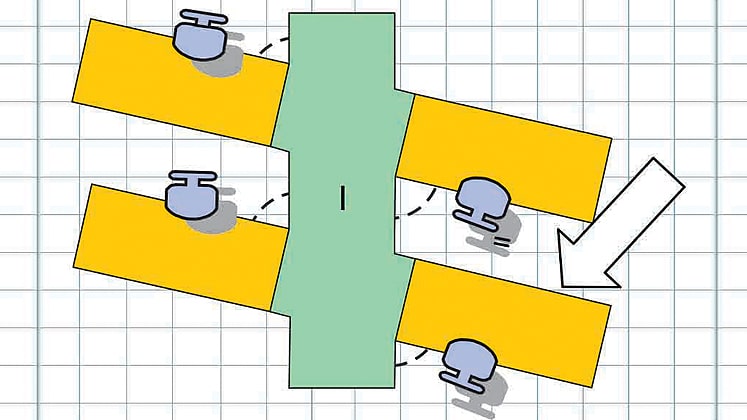
In Layout ‘I’, machine angle on operator’s side is acute (instead of obtuse) and does not result in much benefit. Here output of preceding operator lands directly at the back or on the right of succeeding operator, thus resulting in no benefit of picking. In this angular set up the line supervisor has better physical access to operators for explanation and instructions.
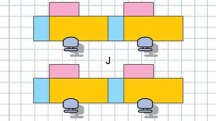
Apart from centre table options sewing machines are also arranged with bins and trolleys. There is no standard layout for variable size of bins and trolleys. Bins and trolleys are made out of metal, plastic, wire mesh; fabric covered and can be fixed and/or detachable. For fixed bin or trolley size one common option is Layout ‘J’. The bin at the left of operator is for pickup and bin at rear of the sewing machine is for dispose off. Here the pieces are not manually emptied rather bins are moved between operations. A dispose bin of preceding operation will work as pickup bin of succeeding operations. The bins or trolleys can simply be swapped.
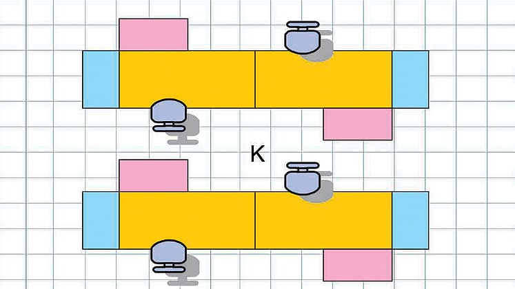
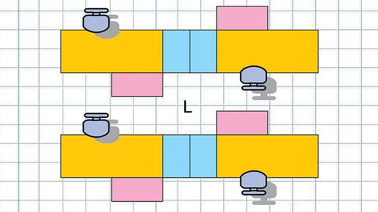
Three close variations of bin or trolley layout is type ‘J’, ‘K’ or type ‘L’. While ‘K’ offers ease in electrical wiring (as motors of both machines are at close proximity), type ‘J’ offers no tangible benefit (except being vaastu-friendly as operators are facing uni-direction). Type ‘L’ tantamounts to centre table situation as pick up bins for both operators are together at centre of the machine line.
Conclusion
All these different types of layout options are to be judiciously used based on area available, access points, light source, air flow, etc. Floor space utilisation and aesthetic and sustainable arrangement of sewing machine is of paramount importance for achieving efficiency in production. Some of the common disadvantages of centre table layout are
• Rigid and non-flexible
• Arrangement of machines is difficult where more than one operation is feeding one operation or vice versa. Resulting cross flow of WIP
• Variable table size is difficult to accommodate
• Separate pick-place-alignj-sew-dispose sequence can not be accommodated
• Vertical space is less utilised.


