There are some operations in the sewing which prima facie seem easy but play a vital role from functional point of view in a garment, the same is true with edge stitch. As is clear from its name, this is performed by making a series of stitches at a fixed distance from the edge (preferably near to the edge), it may be a top stitch also. Many times, the edge stitch is used for decoration purpose to make the garment look neat and more appealing. The key objective of an edge stitch is to keep the fabric layers together and provide a flat appearance to make garment visually more appealing. In that situation the stitch margin from the edge needs to be maintained precisely. Any unwanted variation may cost the value degradation of the garment resulting in a defective product. There are many commercial solutions available in the market including mechanical and electronic devices. In the third article of this series, authors Manoj Tiwari, Assistant Professor, NIFT, Gandhinagar and Dr. Prabir Jana, Professor, NIFT, Delhi have discussed the technological interventions done in this field of Edge Stitching.
As a most common practice to maintain the distance from the edge is to use the edge of the presser foot as reference point (for example say 1/4th of an inch), adding to it most of the sewing machine manufacturers provide the needle plate with scale marked on it showing the distance from the needle point.
It’s a very good option while working for shorter lengths of the edge stitch, but when one has to stitch the longer seams with precision, it’s difficult for operator to maintain the quality as he has to monitor the edge constantly.
The problem has been constantly addressed in the past and a
of developments can be noticed in this area. There have been many patents awarded to the various sewing machine manufacturers, some key patents have been discussed in this article.
There are quite a few solutions available in the market for edge guiding right from very basics to complex ones. Pfaff POWERLINE 3741/3745 is equipped with edge guide with integrated sensor system for seam margin monitoring and documented seam start and end. The distance between seam and material edge is sensed and if it varies from the seam distance (as documented in the memory) programmed (more than the tolerances inside and outside of the documented seam), a warning signal is displayed and operation is stopped.
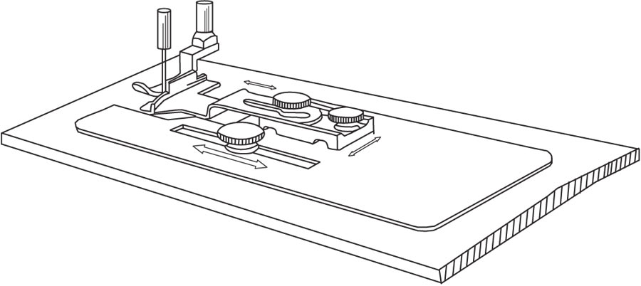
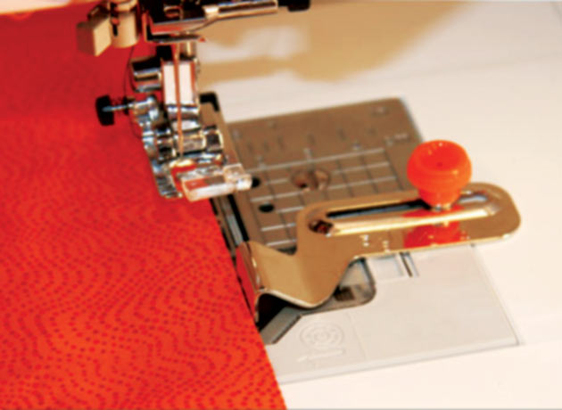
Brother SA 538 seam guide is simple in design so as in functioning. The seam distance from the guide can be adjusted by simply fixing the edge guide on the machine bed with the help of a screw in a scaled slot.
Juki’s Union Special provides special edge guide (part number 36203) for the machines used for flat seams in undergarments capable of single-ply trimming lap seam. The attachment can be fitted on the throat plate of the machine. It can be fitted on either left or right side of the seam and accordingly the single ply (either left or right) can be trimmed in the lap seam.
Probably the first patent (US Patent No. 389152) in the field of edge guiding was awarded to Mary E. Hunter in 1888 for sewing machine gauge. The device can be fitted on any sewing machine bed with help of tightening a screw. There were two basic parts base plate and top plate made of metal strips.
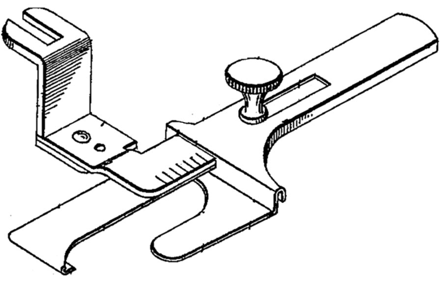
As shown in Figure 1, the base plate consists of a horizontal slot and the position of the base plate can be fixed by tightening a screw in that. There are two vertical slots in the base plate. One (the extreme right slot) is for holding the block and in the other a top plate is fitted. The top plate is again equipped with a slot so that required positioning can be done with reference to the edge of the sewing panel.
Yet another interesting patent (US Patent No. 723121) was awarded in 1903 to William M. Ammerman for developing a tucking device for sewing machines. The invention was specially used for narrow lines of edge stitches (called tucks, like pin tucks). The device was easy in construction and in working also. It provided effective and error free tucks with improved productivity.
As shown in Figure 2, the tucking guide device can be fitted on the sewing machine with the help of a fork arm having a slot to get attached on the presser foot bar. The fork arm is extended and provided with a laterally extended adjustable guide plate. A downwardly bend portion is extended to work as a fold guide. A slot is also provided to adjust the guide plate as required. Another guide (tuck guide) is extended from the guide wall. The position of fold guide and tuck guide can be adjusted with the help of an adjustment screw provided in the slot.
The Singer Machine Company got the patent (US Patent No. 1023335) for developing edge guide for sewing machines in 1912. The primary objective of the invention was to provide improved edge stitching especially for the collar band attached to the collar. The device was equipped with under edge and upper edge guides.
The base plate can be fitted in the machine bed and the edge guide is permanently fixed to it. Another edge guide (upper edge guide) which is actually overhanged is provided with the guide carrier (made of a spring metal plate) and is secured to the base plate at rear end. One sliding intermediate edge guide and fabric separator is provided, which can be adjusted by a screw as required. A stop is also provided to arrest the backward movement of this separator.
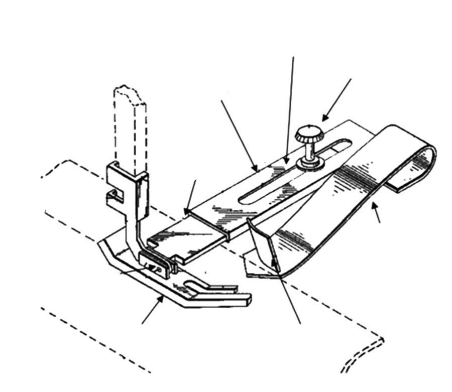
Way back in 1957 (US Patent No. 2781008), Ruth A. Nielsen invented an attachment for guiding the fabric ensuring smooth working surface without any obstruction while stitching. The device was developed in such a way that the guide was combined with the presser foot as permanent part so that smooth function through proper fabric guidance can be achieved while stitching, however the guide can be detached on the same machine while not in use. Another important feature of the guide was its capability of accommodating varying fabric thickness.

As shown in Figure 3, the apparatus consists of a presser foot supported by the presser foot bar. The horizontal bar is connected to the presser foot with the help of lugs that can be pivoted. On the horizontal bar, a sliding element consisting of a flexible metal strip which works like as if a spring is attached. The sliding element can be fixed with the help of a screw and distance from the fabric edge can be adjusted. The flexible strip is attached with a curved guide plate to assist and guide the fabric smoothly while stitching.
In 1972, the Singer Machine Company got the patent (US Patent No. 3693561) for Automatic Edge Guide Mechanism for Sewing Machines. The novel apparatus can be fitted on a single needle lock stitch machine. The device consisted of a sensor to sense edge of the fabric prior to the sewing and the work piece is adjusted by a responsive ring controlled by servo motor to keep the marginal alignment.
This patent claimed the rectification of shortcomings (like damage of fabric, low productivity, limited use for different type of fabrics, etc.) of previously used devices. The invention provided an improved automatic edge guide mechanism for sewing which senses and guides the edge of the fabric alternatively with feeding to produce a seam along a predetermined margin.
The retrofit device may be fitted in a conventional single needle lock stitch machine. The apparatus includes majorly three components: (1) Sensor to sense the fabric edge along with stitching is going on; (2) Servo assembly; and (3) A guide ring assembly fitted to the presser foot bar. In working principle, the fabric is rotated (before the needle for the next stitch is inserted) by the ring by the signal transmitted for individual stitch (based on the predetermined distance of the stitch from the fabric edge) and aligned for the next stitch. Basically the fabric piece is angularly adjusted/corrected with respect to the edge.
Durkoppwerke GmbH, Germany was awarded the patent (US Patent No. 4226197) in 1980 for sewing machine with edge guide. This was an effective but simple in function using an optical device for directing a beam of light towards a reflective surface underlying the fabric on which stitch is going on. The reflective surface is covered until the fabric exposes the reflective surface at the other edge. The optical sensor then generates the signals to control the operation along the edge by turning or adjusting the work piece as per the next sewing stroke. This type of device is very useful where one needs to stitch on edge and have to turn the piece precisely to an angle at several points, for example attaching the pocket on a shirt.

As shown in Figure 4, the sewing machine is equipped with an optical sensor (consisting of photocell and a lens) focused upon the reflective surface attached on the machine bed near to the needle point. The reflective surface is kept covered as the stitching is going on in straight line with the help of edge guide, but as soon as there is a turn needed (for example turn in formal shirt pocket), the reflector surface is exposed and the pulse from the sensor is applied to the control device to initiate the next activity (programme). The turning of the piece and selection of number of stitches in the next step can be selected from the electronically controlled panel provided on the machine. Before this invention the common practice for the edge stitch was using the reflecting material on a template at the particular point where there is turn. This needs a number of templates based on the design variations, in such situations it was not practically feasible solution.
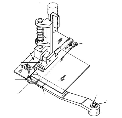
Pfaff Industriemaschinen GmbH, Germany was awarded patent (US Patent No. 4280422) for developing a guide device for sewing machines in 1981. The device was fully mechanical in function yet easy in operation. The invention proved useful while stitching the plies of varying thickness like inseam of jeans. As shown in Figure 5, the device consists of two-fold plates, one is fitted with the presser bar and other is fitted on the machine bed with the help of a screw in a rotatable manner. The main sole part having a U-shape cut (which works as needle passage also), is connected to the presser bar. The first fold plate is connected to this sole part with the help of an angle piece fastened with screws. On the other side of the stitch line, the second fold plate is fitted through a spindle and a snap ring so that the fold plate can be pivoted to this position. The first fold plate consists of a guide edge extending beyond the stitching line and at the same time the second fold plate too has one guide edge extending beyond the stitching line but in the opposite direction of the edge guide of the first fold plate. Thus both the edge guides enable the fabric in “S”-shape fold while edge stitching.
Another interesting and easy development received patent (US Patent No. 4362115) in 1982 by AMF Incorporated, USA for developing method and apparatus for top stitching. The invention was unique in terms of detecting the corners and then automatically reducing and later stopping the needle at the pivot point, once after turning the piece at the
corner, stitching can be resumed as normal. The device was very useful for multi-layered garment parts, which have corners and need precise top stitching after turning inside out like collars and cuffs of a shirt.
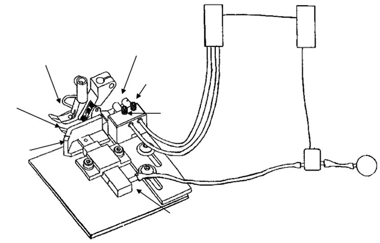
As shown in Figure 6, the device comprises of a guide block having a guide edge mounted on the machine base which is parallel to the stitching direction. The guide block is equipped with two micro switches which can be operated by the feelers made of stiff wires. The feeler wires are pivoted on the axis parallel to the stitching direction and lies on the fabric surface. As the stitching proceeds in the straight line and approaches to the corner, and when there is a corner the first feeler leaves the fabric surface and drops down and by tilting it activates the micro switch. The micro switch is connected to the machine drive and lowers down the machine speed when stitching is approaching near to the corners and once the needle is at the corner, another feeler drops down and makes the machine stitching to completely stop. The raising of the presser foot at this moment lifts the feelers. After turning the piece and lowering down the presser foot, feelers come back to the initial position and become ready for the next action.
To minimize the friction to the garment panel while turning, there is provision for series of the air nozzles directed to the particular angles as per the angle of turn in the garment part being stitched. The time of air jet flow can be predetermined. Once the panel is turned and presser foot is lowered down, the feelers come back in the original position and machine is ready for the next stitching step.
Pfaff Industrial, Germany was awarded a patent (US Patent No. 4467739) in 1984 for seamed material edge guide for sewing machine. The device was specifically designed for stitching at edge while multiple layers are there in the piece, like collars, cuffs, etc.
As shown in Figure 7, in an ordinary single needle lock stitch machine which has a presser foot with slightly raised legs (called as in-feed also) so that the fabric layers can be guided towards the needle smoothly, is further supported by a lay-down.
The device is very effective for edge stitching of multi-layers like top stitching on a collar. As readers may be aware the collar is made of basically three layers where fusing or stiffening layer is sandwiched between top and bottom layers. Once all the three layers are attached, it needs to be turned inside out, creased and ironed properly so that proper shape can be maintained. Ideally the inside edge should be turned 180°, but after ironing it bends only approximately 135° to 150°. This gives bulginess at edges while topstitching. Here in this invention, the fabric layers are pressed continuously by the lay-down and guided with the edge guide. We get effective top stitch by maintaining the required edge distance.
Hams Corporation, Japan was awarded the patent (US Patent No. 5033399) in 1991 for Automatic fabric guide in sewing machine.
The device was based on sensing the presence of fabric edge through a pair of optical sensors and common light source employed near to the needle point on an industrial sewing machine. The device was simple in design as well as in functioning. The device consists of a U-shaped channel (edge guide) with a light source (may be a LED) at the base and two light sensors. The lateral movement of the fabric edge while sewing is monitored through the optical sensing depending on three possible situations of light signals received, that is (1) Signals received by both the sensors, (2) Signals received by one sensor, (3) No signal received by any sensor. Accordingly the control instructions are sent to the control roller to an air motor (may be replaced with pulse motor drive also) controlled by an electromagnetic valve.
The control roller has the outer surface made of polyurethane to avoid any slippage. The roller is connected to the motor through a vertically hung spindle which is freely rotatable. The compensation of the lateral movement of the fabric edge is done by tilting the control roller either left or right from the straight position.
In year 1993, Union Special GmbH, Germany was awarded the patent (US Patent No. 5251557) for sewing machine with an edge guiding device to guide one or more plies of material. The device was capable of an automatically controlled alignment of the garment panel with respect to its edge. The automatically controlled alignment of the work piece with respect to the edge is done with help of guide device having a sensor arrangement for detecting and evaluating the edge position. A motor driven guide wheel to guide the fabric feed and another motor wheels to guide the piece transversely to the desired direction.
A sensor for detecting and evaluating the fabric edge is fitted on the machine head. A work piece guide device is disposed on the sewing machine, this consists of a hollow shaft mounted in the guide housing and a pinion which gets drive from a stepping motor connected through a toothed belt. The other shaft is connected to the hollow shaft fitted with one worm at an end. The worm is further connected to rotatable wheels mounted on pins in a guide wheel. The guide wheel can be adjusted coaxially with the help of a pressure screw.
One of the two motors is connected through a lead from the control unit, which drives the motor in a controlled way based on the signals received from the edge sensor unit fitted on the machine head. Another motor which is connected to the machine drive controls the feed of the fabric being stitched. A carrier plate is also attached to the flanges of the motors and carries a pivotable concave abutment with a leaf spring. To raise and lower down the abutment while loading and unloading the piece, a pneumatic piston arrangement is provided.
Felix Gonzalez was awarded patent (US Patent No. 6725795) in 2004 for developing sewing machine seam adjustment device. The width of the seam can be adjusted automatically based on the feedback received from a sensor detecting the position of sewn edge.
As shown in Figure 8, the device consists of a clamping foot having two presser foots – outside presser foot (Adaptable to transverse displacement to adjust the seam width) and the inside presser foot. The outside presser foot is suspended and can be adjusted with reference to the inside presser foot. The seam adjustment device includes an edge guide, a sensor (a light based signal sending and receiving unit), a displacement transducer (basically a piston to adjust the position of the edge guide), and one edge guide along which sewing is done.
As the sewing is going on, the seam edge passes through the sensor, which checks for the correct seam width. The edge guide is fitted at a required distance from the needle point. The sensor has a light sending unit as well as a light receiving unit. Once the edge is sensed, the light is sent through a pipe (by scattering, refraction and reflection). When there is any deviation in the seam width, the adjustment signal is carried away to the power supply device and subsequently to the control switch, which controls the transducer by operating a valve to adjust the seam. When valve is activated, a fluid (may be compressed air or liquid) is permitted to flow to operate the transducer. The outside foot is suspended on a wire and can be moved/traversed based on the seam width and this can be regulated with help of an adjust screw. This facilitates a range by which the foot can be displaced maximum inside to make the widest seam.